SOLIDWORKS Electrical

Brewing with Electricity: The SOLIDWORKS Brewery: Lautering and Sparging

Up to this point, our grains have been soaking in water that has been set to the perfect temperature in order for us to extract as much sugar from the grain as possible. With the slim chance that we left some sugar in with the grain, we need to take a few additional steps – which are known as lautering and sparging. In large scale operations that you might see at one of the many breweries around North America, mashing, lautering, and sparging are typically performed in separate tanks. But due to the fact that this equipment is for personal use (and has been set up in Earl’s living room), we perform these steps in the same kettle. It’s all about efficiency. This same concept applies when designing our schematics. One particular feature of SOLIDWORKS Electrical can help improve our efficiency AND our effectiveness during the design process. Project Macros is that feature and it can be extremely powerful. It’s kind of like the old copy-paste option, but way smarter and way faster. We can take a symbol with associated part information and save it off for future use within our current project or in any other project we so choose. We can also copy multiple symbols and all the wires connecting those symbols. To make it even better, we can copy entire sheets or multiple sheets and create a macro out of them as well. As I mentioned already, (and as you can probably tell) Project Macros is my favorite feature in the software. We can even take our macros to the next level by incorporating them with the Excel Automation tool as well as the PLC configuration tool – both of which can help us make our designs even faster. So be sure to check out Episode 4 in our “Brewing with Electricity” mini-series where we conduct the lauter and sparge phase to increase the sugar in our wort and discuss the various methods of symbol creation within SOLIDWORKS Electrical. SOLIDWORKS Electrical If you are still looking for more great information on SOLIDWORKS Electrical including topics such as “Understanding Project Macros,” check out our videos on these more detailed topics at my.solidworks.com – simply search for Electric Brewery. If you’re a fan of Twitter, you can follow me at @SWECAD

SOLIDWORKS Plastics

SOLIDWORKS Plastics At The Beach

By using SOLIDWORKS Plastics we can simulate the injection molding manufacturing process Well summer is just around the corner and my family is chomping at the bit to get down to the beach. Last weekend I cleared out the garage and dug out all our children’s beach gear, buckets, spades, and alike. Which got me thinking, could I a mechanical engineer with minimal plastics training, design a new sandcastle bucket that looks right and can be successfully manufactured? In order to keep the cost down, I decided that my sandcastle will be manufactured using the injection molding process. Creating the geometry in SOLIDWORKS is a breeze, a few extrudes, some patterns, fillets, a shell feature and I am good to go. Lastly, by running a draft analysis I know that the geometry can be ejected from the mold. But as every engineer knows, the geometry is only half the story. The big questions are, can this part design be injection molded, and is the resulting part acceptable? By using SOLIDWORKS Plastics we can simulate the injection molding manufacturing process to ensure that not only is the part design moldable, and that the resulting part is fit for sale. The first set of questions I need answered by SOLIDWORKS Plastics are “Is my part design capable of being injection molded, and where do I place my gate location?”. The least expensive form of injection molding uses a cold runner system with the gate located on the parting line. So I now have a new question, “Do I gate from the short side of the sandcastle, or gate from the tall side”? Doing this by trial and error after machining the mold is not an acceptable option, as it is far too expensive of a test procedure. By using SOLIDWORKS Plastics, I can run multiple analyses as my testing method and all it costs me is CPU time and not much else after that. My first test has the gate located on the short side, shown by the green arrow in the image below. SOLIDWORKS Plastics reports a Fill Time of 9.5 seconds and required Injection Pressure of 74.2 MPa. This part design has a large part volume, so the lengthy fill time is reasonable and the injection pressure is well within most machine maximum injection pressure capabilities of 200 MPa. My first question regarding the moldability has been answered. Yes, my part design can be molded. Although, at first glance the results look good, there is an issue with my gate location on the short side. SOLIDWORKS Plastics predicts a large and visible Weld Line on the tall side of the part, shown below by the red arrows. The reduction in structural integrity caused by the Weld Line is not my concern, as this is a beach toy and will not be supporting extensive loads. What does concern me is our company primarily uses metallic-flake colorant in our plastic materials, and metallic flake noticeably gathers along Weld Lines and is an aesthetic blemish on the molded part surface. In my second analysis, I gated the part from the tall side of the sandcastle. The Fill Time and Injection pressures are similar, and now the Weld Line results show two weld lines in less noticeable locations. They are much smaller than original weld line and are spaced further apart. So gating from the tall side is my best option. I now have the gate location squared away, what kind of runner design and mold design should I use for production? A quick chat with a friend suggests a four cavity layout with an “H-Type” runner system would be a good starting point. Once again using SOLIDWORKS Plastics, I can simulate the manufacturing process so I can validate the moldability of my part design. Now let’s make sure my “H-Type” runner design is my best option before cutting any metal and incurring unnecessary expenses. Due to the height of the sandcastle design, using a sprue inlet diameter of 5.0 mm and a standard sprue draft angle of 3.0 degrees results in a sprue outlet diameter of 31 millimeters. The 31 mm diameter runner will take about seven minutes to cool down sufficiently to eject from the mold. Even I know a seven minute cycle time is no good for production. Once again SOLIDWORKS Plastics is guiding me towards a better manufacturing process for my part design. I make the decision to not use a parting line runner system for this mold layout. The first step to reduce the sprue height is to gate from the top of the sandcastle by using a “three plate, cold drop, center gate”. This is a similar approach to how 5 gallon buckets are injection molded, except those use a much more expensive hot runner system. The results from this center gate analysis shows that that there are no substantial weld lines to be seen when gated from the top face. Since the center gate on the top face is the optimal gate location, this will be the runner design used to injection mold the highest quality part, using the most cost effective design. SOLIDWORKS Plastics In plastic part design, the geometry is only half the story. SOLIDWORKS Plastics should be used throughout your design process to validate your part design, runner design, and mold design saving you both time and money.
Bicycle

The Whirlwind Engineering History of the Bicycle

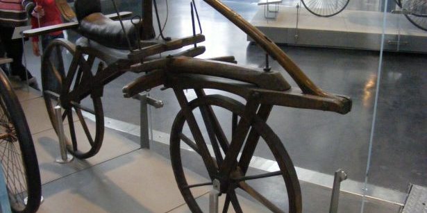
Bicycle History- Stridewalkers, Boneshakers, Penny Farthings. The bicycle has been privy to some curious iterations. Fetch your helmet, here’s a whistle-stop tour of the bike’s 220-year history. Who needs nuclear power when you’ve got a bicycle? That’s what the nation’s listeners of UK Radio 4 program You & Yours decreed in 2005 when they voted the bicycle as the most significant technological innovation since 1800. In winning the poll – emphatically – the humble bike also batted away competition from the computer, radio, the internet, communications satellites, internal combustion engines and the germ theory of infection. Not bad. But what’s so special about two wheels, a frame, and a saddle? Well, it turns out there’s rather more to it than that. So much so that today’s performance bikes are as much the work of F1 engineers as bike manufacturers. Yep, the bike’s wheels have rolled an awfully long way since the clunky wooden specimens of the eighteenth century. Today the world’s one billion bikes represent the most efficient vehicle the world has ever seen. Behold its history. 1817: The world’s first bike? Step forward German inventor Karl Drais, who in 1817 patented the design for his Laufmaschine (translation: running machine). Riders straddled a wooden frame and – in the absence of pedals and chain propulsion – pushed their feet along the ground to get the wheels moving. Hence the distinctly sci-fi-sounding nickname: Stridewalker. 1839: The birth of pedal power Kirkpatrick MacMillan, a Scottish blacksmith, makes what would become the most influential addition to the story of the bicycle: a mechanical crank-drive system attached to the rear wheel. Hello pedals, goodbye scuffed shoe soles. 1863: The Boneshaker becomes the world’s first mass-produced bicycle Building on MacMillan’s crank-drive innovation, Pierre Michaux (another blacksmith) and his son Ernest developed the world’s first mass-produced bicycle in 1863. It was called the velocipede and had flanged wheels that endowed it with the unique ability to ride along rail tracks. Hmm. Back on the cobbled streets of the nineteenth century, the wooden-rimmed wheels were particularly unforgiving – earning Michaux’s bicycle the nickname ‘Boneshaker’. 1870: The birth of the penny-farthing It might have looked ridiculous, but the Penny-Farthing was built to serve a very practical need: the need for speed. Without gearing, the only way to increase bicycle speed was to increase the size of the wheel attached to the pedals – and the enhanced availability of steel meant large wheels were a simple engineering challenge. Unfortunately, penny-farthings were incredibly difficult to mount, much less ride and became the preserve of the brave, the skilful and the foolish. 1879: The birth of modern bicycles During the late 1870s, a number of inventors developed an alternative to the penny-farthing, marketed as the safety bicycle for obvious reasons. With a chain drive that allowed the rider to sit at the centre of the frame, a height that made it easy for riders to reach the ground and wheels that were broadly the same size, the safety bicycle fuelled the surge of bicycle popularity in the 1890s and the birth of companies such as Raleigh and Schwinn. The same design is used to this day. Yep, for the last 140 years all we’ve been doing is tweaking a design classic. 1888: Watch where you tread Scottish veterinary surgeon and inventor John Dunlop are the first to add pneumatic tyres to a bike while successfully attempting to make his son’s tricycle safer. He then brought his innovation to cycle racing and it was quickly adopted. The following fifty years was a time of major innovation in terms of gearing, brakes and derailleurs. 1940: Changing gear gets simple Italian bicycle component manufacturer par excellence Campagnolo invented a derailleur called the Cambio Corsa. It’s revolutionary. Instead of stopping and flipping their rear wheel to change gear, riders can flick a rod located above the rear wheel. 1986: The clamour for carbon The 1980s dawned an era of serious engineering innovation for bikes. Suddenly the everyday consumer could purchase BMXs, mountain bikes, road bikes, commuter bikes, elite racing bikes, tandems and more. One of the most major innovations of the 80s comes when manufacturer Look produced a racing bike with a carbon fibre frame. Ridden by Greg LeMond, Look’s KG86 wins the 1986 Tour de France. 1990: The UCI defines what a bicycle is UCI, the governing body of cycling, defines what a bicycle is. All race bikes must abide by these parameters and bicycle engineers everywhere have a strict set of limitations within which to innovate. What’s the future of bikes? The UCI parameters mean that the basic design of bicycles for competitive races isn’t going to change anytime soon. That doesn’t mean visionaries can’t have their fun with concept bikes and commuter bikes. Oh and lest we forget the revolutionary trikes that Van Raam have developed in SOLIDWORKS for those with mobility issues and their carers.

SOLIDWORKS Visualize

Visualize 2018 Beta is Here!

As you prepare for a summer of fun in the sun, there will likely be a rain shower or two…or several depending on where you live. What to do to fill that time? Give SOLIDWORKS Visualize 2018 Beta a try! Do you have SOLIDWORKS CAD but haven’t downloaded your complimentary Visualize Standard* seat yet? Now’s the perfect time to get started and explore Solidworks Visualize 2018 Beta. We’ve added loads of new features to keep you ahead of the curve and ahead of your competition. We’ve also refreshed the user interface and simplified the picks & clicks to make your lives easier. Read on to see a small glimpse of what’s new in Visualize 2018 and helpful links to get started with 2018 Beta today! REFRESHED THE USER INTERFACE DESIGN The biggest, and likely first new feature you will see, is an updated look for Visualize 2018. Our goal was sleek, simple and clean. This new look and feel brings Visualize into the modern era, while making it easier to use at the same time. There’s also a way to switch to between two preset themes, but you’ll have to find that one out for yourself. Gotta leave something for you to explore. CREATE VIRTUAL REALITY CONTENT Have a VR headset and wish you could teleport yourself into your Visualize project? Well wish no more! Visualize 2018 allows you to create ‘Spherical’ cameras which render out a single flattened-spherical image. This image can then be converted to use with any VR headset (even a $15 Google Cardboard!). With this new Spherical camera enabled, you can create proper stereo (left eye, right eye) as well. But the coolest part about this new feature is you can also create animations for VR with this new Spherical camera! Give it a whirl and give us your Beta feedback so we can improve this workflow for our major 2018 release this October. (Visualize Professional only) NEW LIGHTS EVEN EASIER WAY TO PLACE THEM Have you struggled with placing your lights in your scene? Or wanted to move your light to illuminate an exact spot on your model? Or maybe you design interior spaces and want your renders to finish at a fraction of the time? Then this one’s definitely for you. We’ve introduced a new way to instantly place lights in your scene, just by clicking on the model where you want the light to illuminate. This comes with new ‘Area’ light types (sphere, plane, tube, disc) to help recreate any real-world lighting environment. They are much easier to set up and control the lighting of your scene. It’s very similar to the ‘emissive plane lighting technique’ that many of you know very well. Here’s the real kicker…these new Area lights work in Fast mode! Before only Accurate mode supported emissive lighting. This means you can now use Fast mode for your interior scenes! Have fun with this one. (Solidworks Visualize Professional only) There are loads of new features, improvements, and enhancements in Solidworks Visualize 2018 Beta…too many to list here. Experience the awesomeness for yourself right now!

SOLIDWORKS

How Does Home Licensing for SOLIDWORKS Work?

SOLIDWORKS users have long enjoyed the ability to use their software from both their home/mobile and work offices. How is this accomplished without running afoul of the EULA (End User License Agreement), which only permits one license enabled on any one computer at any one time? In our previous two blog posts, we examined perpetual licenses (Standalone and SNL) and term licenses. Let’s first look at standalone licenses. Standalone licenses are intended for an individual user of SOLIDWORKS or a related product. It uses an activation process to enable your license to operate after installation. Once the software is activated on a computer, it remains permanently enabled until such time as you choose to deactivate it. If you would like to run SOLIDWORKS on another computer, you must first deactivate (using “Help – Deactivate Licenses”) the computer holding your SOLIDWORKS_License. The Activate/Deactivate function inside the software allows you to install SOLIDWORKS on as many computers as you wish – ensuring only one computer is operational with SOLIDWORKS at any one time SOLIDWORKS Standalone / perpetual licenses with subscription service for an individual user as displayed inside the application. If you would like to run SOLIDWORKS on another computer, you must first deactivate (using “Help – Deactivate Licenses”) the computer holding your SOLIDWORKS license. The Activate/Deactivate function inside the software allows you to install SOLIDWORKS on as many computers as you wish – ensuring only one computer is operational with SOLIDWORKS at any one time. Standalone licenses are activated/deactivated under the Help menu in SOLIDWORKS allowing you to run the software on multiple computers. Users can borrow or hold a license/s for up to 30 days. SNL license usage showing five total licenses, three of which are in-use, one license borrowed, and one license free. SNL, or network licenses (sometimes referred to as “floating” licenses), also uses an activation process but only for the server, which monitors concurrent license usage. The individual clients running SOLIDWORKS or a related product or add-in retrieve a license each time the software is started, and return the license each time it is closed so that another user can use it. SNL clients can “borrow” a license temporarily for up to 30 days, after which time if the license has not been returned, the server will automatically do so. The status of license usage can be checked at any time. Any borrowed licenses will also display in this pane. Home/mobile use is of course possible for term licenses as well. Term licenses, from an installation and entitlement perspective, behave in the same exact manner as standalone licenses, i.e., license access is granted through the activate/deactivate process. If a user would like to run a term license on another computer, the license must first be freed up using Deactivate license under the Help menu as described earlier. This concludes our blog series about licensing with SOLIDWORKS. If you would like to see other articles related to this topic, please comment below and we’ll consider it in a future topic. If you have any difficulties managing your license, our experienced support team is ready to help you out. We hope these tips help you stay productive while working from home. To Get SOLIDWORKS Licenses Cost request for quote and get instant SOLIDWORKS price from the best SOLIDWORKS reseller Related SOLIDWORKS Articles Can You Permanently Buy SOLIDWORKS Software License? What are the different Solidworks Software in India and How to buy? What’s New in SOLIDWORKS Visualize 2022 USE OF SOLIDWORKS EXPLORER

SOLIDWORKS

MIT Students Take Innovative New Product from Dorm Room to Market in Record Time

SOLIDWORKS – MIT Students Take Innovative New Product Any college student will tell you that coffee is often a key ingredient to surviving those stressful days of college when hours of slumber are in short supply. When cost-conscious college students splurge on expensive to-go coffee from places like Starbucks or Dunkin Donuts, they want to savor every drop of that hot, precious beverage. Get sidetracked for a minute, however, and that hot beverage is suddenly not so hot, literally. Two recent MIT graduates created the Coffee Cookie to extend the amount of time your coffee stays warm. Victoria Gregory and Gabriel Alba are two Mechanical Engineering students who just recently graduated from MIT. Conceived by the duo during an exercise in a Product Engineering class, the Coffee Cookie is a small circular device that attaches to the bottom of a disposable coffee cup and heats the liquid within up to 90 degrees Celsius, and resembles…you guess it, a cookie. Powered by a rechargeable battery, the device can be recharged for daily reuse. After conducting some initial research via an online survey of 300 people, Gregory and Alba determined that respondents—especially millennials—are likely to pitch takeout coffee once it loses heat, typically tossing the final third of the cup. The research results indicated that the device would not need as big of a battery as initially thought, making their burgeoning idea doable.   Bringing an idea to life Hatching an idea for a new product is just the first of many arduous steps for startups. Like any entrepreneurs, Gregory and Alba had to figure out how to bring their idea to life. During the pair’s sophomore year, they both learned how to use SOLIDWORKS for a class project to design a robot. While Gabriel had previous experience using a suite of Autodesk products during high school, he felt more comfortable using SOLIDWORKS. “SOLIDWORKS just clicks more with the way I think and the way I design products,” says Alba. The pair pitched their idea to the board of the Sandbox Innovation Fund Program at MIT where they were awarded $10,000 to seed their startup. Over winter break from school, the two embarked on creating prototypes of the device. Making use of both dorm rooms and student maker spaces, the two put in long hours over those four weeks, sometimes up to 24 hours straight. In a single day, they designed and 3D printed the device so they would have physical proof of concept. While the first one lacked the sophistication of typical prototypes—part of which was held together with hot glue—the pair soldiered on to creating several more prototypes that would fit a variety of disposable cups. With a very limited budget and a tight timeframe with which to work, the students knew that any mistakes made along the way could jeopardize the project. To prevent that from happening, the two unleashed the power of SOLIDWORKS Plastics Simulation software to simulate the plastic flow into the plastic molds that would be used to create the plastic casing for the device’s battery.   SOLIDWORKS Plastics “SOLIDWORKS Plastics would tell us what size to make the gates and how to set up our parameters,” says Gregory. “An experienced mold maker could probably make an educated guess but we wouldn’t know. If we had a part short shot, we would have had to re-make the whole model so using the software saved us a lot of time over doing it from scratch.” To create the printed circuit board (PCB), they used CircuitWorks so they could closely coordinate the design of both the mechanical and electrical components of the device, again mindful of the impact any error would have on their short design cycle. “SOLIDWORKS is such a great learning tool and saved us so much time to do this project while maintaining a full class load at MIT,” says Alba. “SOLIDWORKS has been our best friend for this project.” Once the prototype was complete, the pair decided to ramp up to 1,000 units. They ordered 1,000 batteries from China and spent their time since graduating from MIT in May assembling the units. Recently Gregory and Alba moved to New York City to explore possible avenues through which they can sell their Coffee Cookies to consumers, where they will target mothers, college students, young professionals, and busy executives who must get their caffeine fix on the run but still like it hot.