Automotive component design is rarely a simple matter of creating a 3D model and sending it to manufacturing. Engineers are working with tight tolerances, changing material requirements, OEM specifications, cost targets, and delivery schedules that leave very little room for mistakes.
That is one reason SOLIDWORKS has become a practical choice for many automotive component manufacturers and engineering teams. The platform brings together part and assembly modeling, sheet metal, weldments, simulation, documentation, and data management in a connected design environment.
For tier-1 and tier-2 suppliers working on brackets, housings, transmission components, fixtures, tooling, and other automotive parts, this connected approach can make a noticeable difference in day-to-day engineering work.
In this guide, we will look at how SOLIDWORKS automotive component design workflows typically work, which tools are most useful, and what the Craftsman Automation case tells us about the practical benefits of adopting a structured CAD workflow.
Why SOLIDWORKS Fits Automotive Component Design
Automotive suppliers usually do not design components in isolation. Much of the work starts with information supplied by an OEM or another customer, often in the form of 3D CAD data or STEP files.
When the supplier and customer are working with compatible CAD environments, there is less opportunity for translation problems, version confusion, or unnecessary rework. That matters in automotive manufacturing because a small misunderstanding in a drawing or model can eventually become a tooling or production delay.
Another advantage is the range of tools available within the SOLIDWORKS environment. Automotive teams can work with sheet metal parts, welded structures, molded and cast components, simulation studies, manufacturing documentation, and product data management without having to build the entire workflow around disconnected applications.
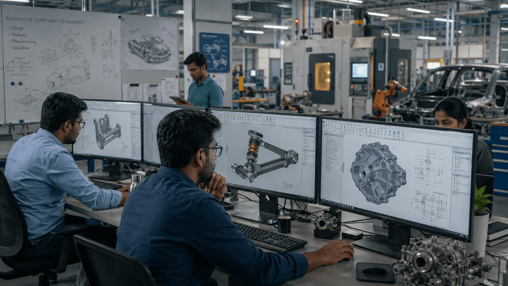
Core Workflows in SOLIDWORKS Automotive Component Design
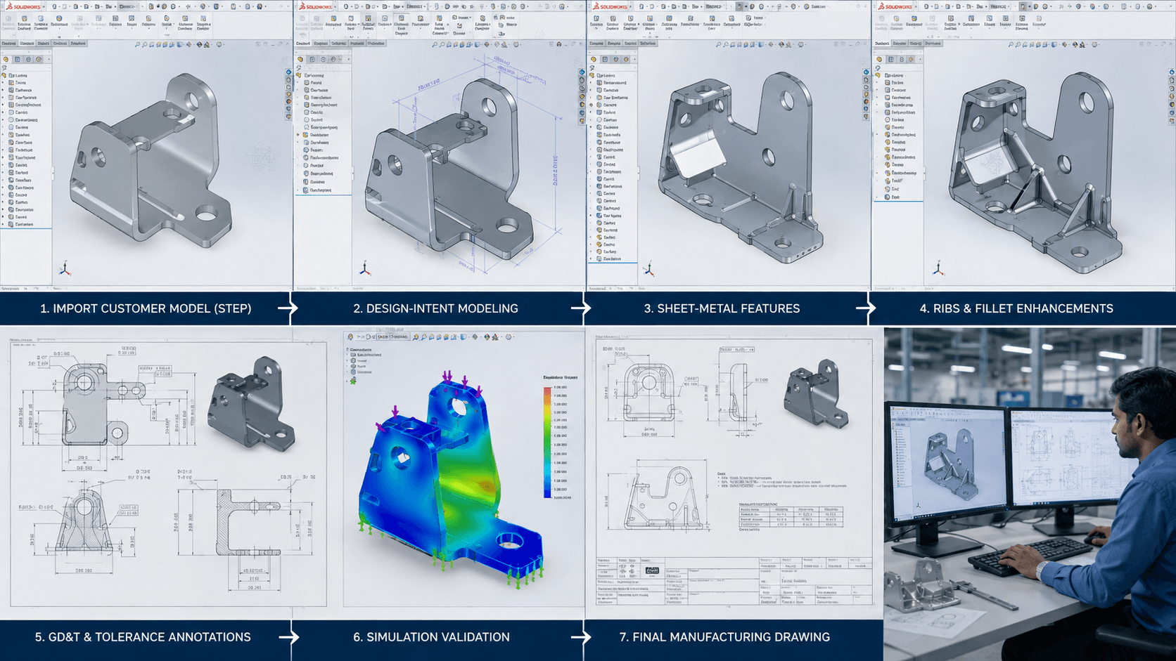
Although every supplier has its own processes, several workflows appear repeatedly in automotive component design.
1. Part Modeling from Customer-Supplied Data
Many projects begin with a customer’s native 3D model or a neutral format such as STEP.
The engineer can import the geometry and then build the manufacturing requirements around it. Reference features, draft angles, fillets, ribs, mounting features, and other details can be incorporated while maintaining the intended definition of the customer-supplied component.
This approach is particularly useful when the supplier needs to manufacture a component or create tooling around an existing customer design.
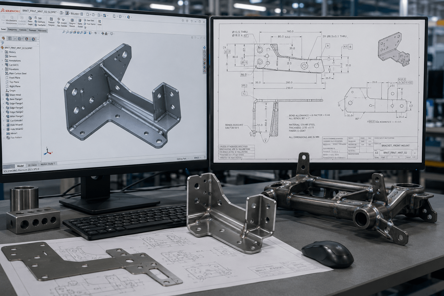
2. Sheet Metal and Weldment Design
Brackets, mounting frames, structural housings, fixtures, and jigs are common requirements in automotive engineering.
SOLIDWORKS Sheet Metal provides tools for developing formed components and generating flat patterns, while the Weldments environment is designed around structural members and welded assemblies.
For engineers, this means the design can be developed with manufacturing considerations in mind rather than treating fabrication as a separate activity at the end of the process.
3. Tolerance Stack-Up and GD&T
Automotive components often have to fit accurately with other parts, particularly in mating and rotating assemblies. That makes tolerancing an important part of the design process.
Teams can apply GD&T information to the 3D model using Model-Based Definition (MBD) workflows and perform tolerance stack studies before tooling is released.
The benefit is straightforward: potential interference and fit problems can be identified during engineering instead of being discovered after a component reaches the shop floor.
4. Simulation-Driven Validation
Simulation is most useful when it is treated as part of the design process rather than something that happens only after the model is finished.
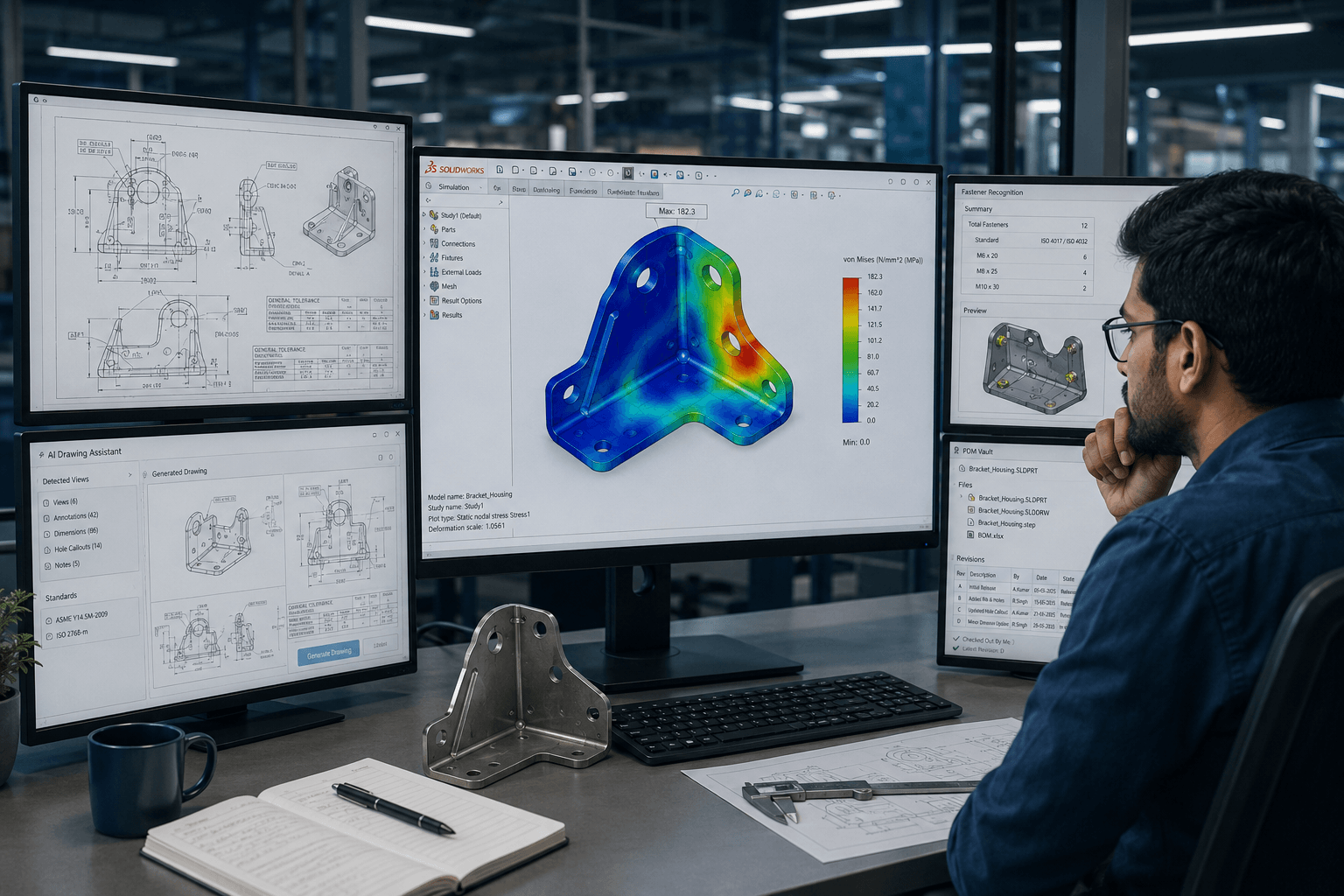
With SOLIDWORKS Simulation, engineers can evaluate components such as brackets and housings under defined load conditions. Depending on the analysis requirements, teams can investigate structural, thermal, vibration, and other engineering behaviors before committing to physical tooling or prototypes.
This can help engineers identify weak areas earlier, compare design alternatives, and make changes while the cost of modifying the design is still relatively low.
SOLIDWORKS 2026 also introduced improvements around simulation setup and validation, giving engineers more control over load definitions and helping identify certain setup issues earlier in the workflow.
5. Tooling and Fixture Development
For an automotive component manufacturer, designing the component is only part of the job. Tooling and fixtures often represent a substantial portion of the engineering workload.
A new component variant may require a corresponding fixture, jig, die, or other manufacturing aid. Because these designs are directly connected to the component geometry, having the tooling and component within the same CAD workflow can make design changes easier to manage.
6. Drawing Automation and Documentation
Automotive drawings can become surprisingly dense. Dimensions, GD&T callouts, weld symbols, hole information, revision details, and manufacturing notes all need to be accurate and easy to interpret.
SOLIDWORKS 2026 introduced AI-assisted drawing capabilities, including the Auto-Generate Drawing functionality, which can propose drawing views and dimensions. Fastener and hole recognition capabilities can also reduce some of the repetitive work involved in preparing engineering documentation.
These features do not eliminate the need for engineering review. Instead, they can help reduce repetitive drafting work so engineers can spend more time checking the design and manufacturing requirements.
7. Data Management and Revision Control
Once several engineers begin working on shared assemblies, revision control becomes increasingly important.
A released drawing should not be silently replaced by an older or unapproved version. SOLIDWORKS PDM provides check-in and check-out controls, revision history, and approval workflows that help teams maintain control over engineering data.
This becomes particularly valuable when OEM-driven design changes are happening frequently or when design teams are distributed across different locations.
Key SOLIDWORKS Tools for Automotive Engineering Teams
There is no single SOLIDWORKS tool that solves every automotive engineering problem. The value comes from combining the right capabilities into a consistent workflow.
- SOLIDWORKS Professional / Premium: Core 3D design capabilities with additional tools for professional engineering workflows.
- SOLIDWORKS Simulation: Integrated FEA capabilities for validating component performance under defined engineering conditions.
- SOLIDWORKS Composer: Useful for technical illustrations, assembly documentation, and work instructions.
- SOLIDWORKS PDM: Helps manage engineering files, revisions, approvals, and controlled access.
- Sheet Metal and Weldments: Purpose-built workflows for fabricated components, brackets, frames, fixtures, and structural parts.
- Model-Based Definition (MBD): Supports teams that are moving toward drawing-light or drawing-less manufacturing information.
The right combination depends on the type of components a company designs and manufactures, the complexity of its assemblies, and how much simulation, documentation, and data management the engineering process requires.
Case Example: Craftsman Automation
A useful real-world example is Craftsman Automation Pvt. Ltd., a Coimbatore-headquartered manufacturer with multiple plants across India and significant exposure to automotive customers.
The company works with automotive customers including Daimler India Commercial Vehicles, Tata Motors, Ashok Leyland, and Mahindra & Mahindra, along with applications involving engine heads, engine blocks, transmissions, gearboxes, and other components.
Before 2004, Craftsman developed tooling and fixtures using 2D AutoCAD drawings supplied by customers. As customers increasingly began providing native 3D model data, the company standardized on SOLIDWORKS across its design teams.
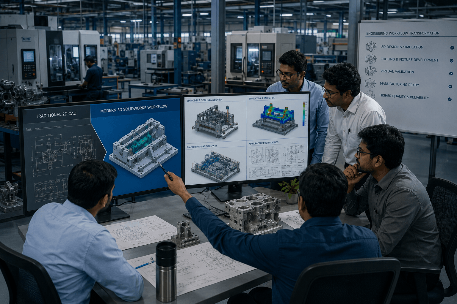
According to the SOLIDWORKS customer case study referenced in the source material, the results were significant. Craftsman reported a 40% increase in manufacturing output, an approximately 30% reduction in production cycle time, and improvements in overall product quality.
The company also expanded into mold and cast-part applications. Another important part of the transformation was incorporating FEA validation into tooling projects and having customers review and approve simulation results before tooling production began.
The bigger lesson is not simply that one company achieved specific improvements. It is that a structured engineering process can create benefits that extend beyond modeling speed.
Using a CAD platform that aligns with customer data, validating designs before manufacturing, and controlling revisions throughout the process can collectively improve engineering throughput and reduce avoidable production problems.
What This Means for Automotive Component Manufacturers
The Craftsman example highlights an important point: CAD software delivers the most value when it becomes part of a disciplined engineering process.
Simply purchasing SOLIDWORKS will not automatically reduce cycle times or improve quality. The benefits are more likely to appear when teams establish repeatable workflows around:
- Customer model import and design intent.
- Manufacturing-aware part modeling.
- Sheet metal and weldment design.
- GD&T and tolerance management.
- Early simulation and validation.
- Tooling and fixture development.
- Automated and standardized documentation.
- Revision and approval control through PDM.
That is where the connected nature of the SOLIDWORKS environment becomes useful. Engineers can move from design to validation to documentation without constantly rebuilding the same information in unrelated systems.
Frequently Asked Questions
Do I need SOLIDWORKS Premium for automotive component work?
Not necessarily. SOLIDWORKS Professional covers many of the core requirements for automotive component design, including modeling, sheet metal, and weldments. Premium becomes more relevant when advanced surfacing or reverse-engineering capabilities are important to the type of components being designed.
Is SOLIDWORKS Simulation enough for automotive components?
For many bracket, housing, and fixture-level validation tasks, SOLIDWORKS Simulation can provide the required analysis capabilities while remaining within the SOLIDWORKS design environment.
However, highly specialized applications such as crash analysis, NVH, or full-vehicle simulation can require dedicated CAE solutions.
Is PDM really necessary for a small automotive engineering team?
It can be more useful than a small team might initially expect. Even when only a few engineers are sharing assemblies, formal check-in/check-out procedures and revision tracking can prevent costly mistakes involving overwritten or outdated production files.
Can SOLIDWORKS handle sheet metal and cast or molded automotive components?
Yes. Sheet Metal and Weldments can be used for formed and structural components, while standard part modeling and mold-related tools can support cast and molded geometry within the SOLIDWORKS environment.
Final Thoughts
Automotive component design rewards engineering discipline more than raw modeling speed.
Good tolerancing practices, early simulation, controlled revisions, and manufacturing-aware modeling can make a bigger difference to a project than simply creating the 3D model faster.
That is where SOLIDWORKS can fit well into an automotive engineering workflow. Sheet metal, weldments, simulation, documentation, and data management can work together around the same design data, which helps teams maintain continuity from customer requirements through manufacturing.
The Craftsman Automation example provides a useful reminder of what can happen when that approach is implemented consistently: improvements can extend beyond the CAD department and show up in manufacturing output, cycle time, and product quality.
Need Help Building a SOLIDWORKS Automotive Workflow?
If your engineering team is working with automotive components, tooling, fixtures, or manufacturing documentation, the right SOLIDWORKS workflow can help bring design, simulation, documentation, and data management together.
Talk to our SOLIDWORKS implementation team to assess your current workflow and identify opportunities for improvement.